
Edit planset sheets and place equipmentBeta
Place equipment on the site plan, change a value on a sheet, edit the electrical diagram, and regenerate the sheets that are out of date.
After the studio builds a planset, you can fix what a sheet shows without leaving the studio. Place equipment on the site plan, change a value on a sheet, and edit the electrical diagram. Planset Studio is in beta. Contact solarOS support to turn it on for your company.
Before you start
The planset has a finished build, so the sheets show down the left of the studio. See Create, check, and review a planset.
Use the tabs
The tabs on the right of the studio change with the sheet.
- Every sheet has Inputs, Selection, Checks, and Builds, in that order.
- The electrical diagram adds a second row with Tie-in and Schedule.
- The site plan adds a second row with Placements.
Place equipment on the site plan
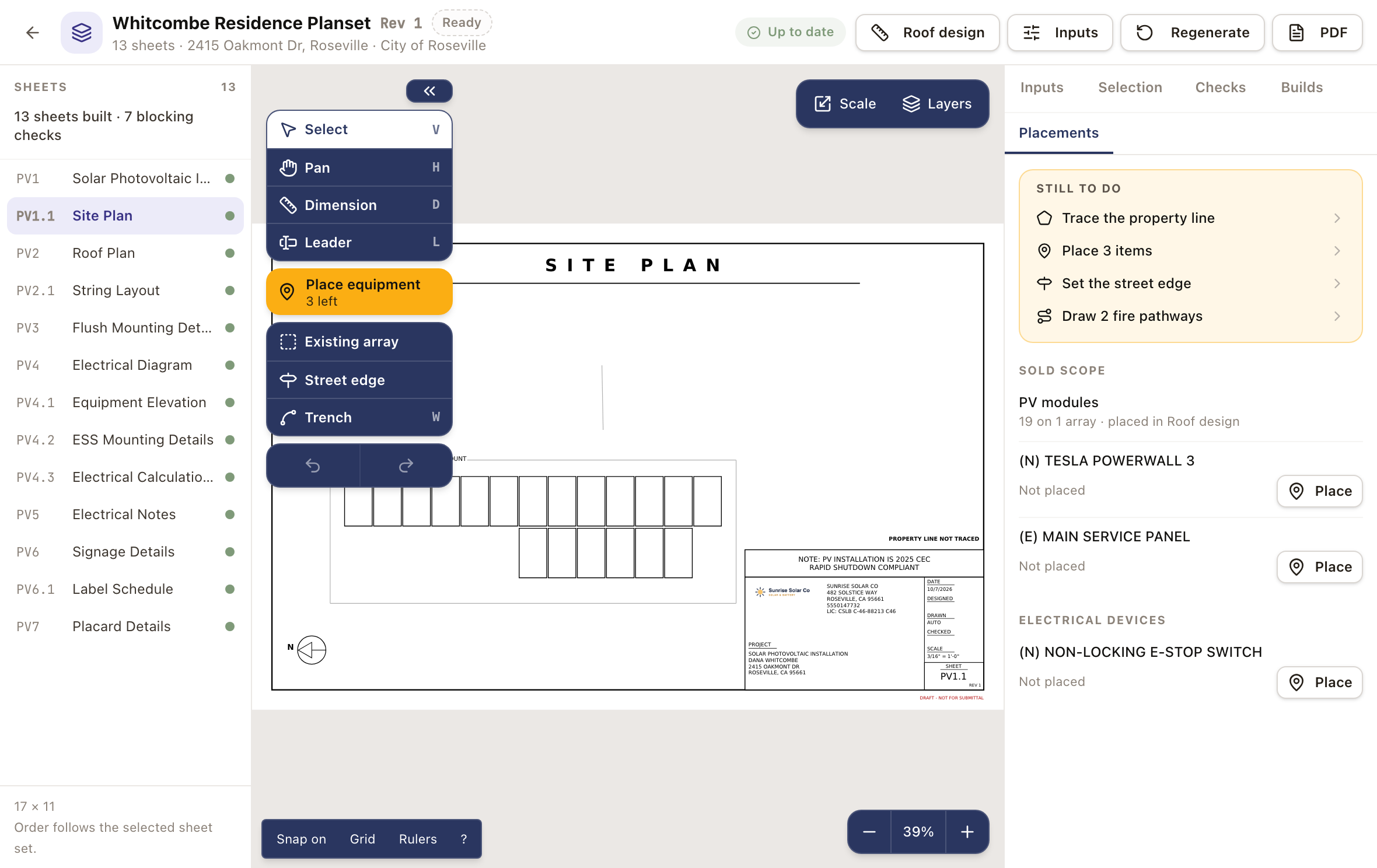
- Click the site plan sheet (PV1.1) in the list on the left, then click the Placements tab.
- Still to do at the top lists what the site plan still needs, such as Trace the property line or Set the street edge. Click a line to open its tool. The list goes away when nothing is left, and it never prints. Sold scope lists the PV modules and each other piece of equipment on the job. Electrical devices lists every device from the planset inputs. Each row reads Not placed, Placed, or a count such as 2 placed or 1 of 2 placed. Modules are placed in Roof design, so their row has no button.
- Click Place on a row, or click Place equipment in the toolbar. A card names the equipment you are placing. Click near a wall. The equipment snaps to the nearest exterior face of the building.
- The studio places one for each unit sold. When the count is met, Place goes away and the tool returns to Select. To add an extra, click Place another on its row. To move a unit, click Move on its row, then click near a wall. To take one off the plan, click Remove on its row. Undo brings it back.
- Use the other toolbar tools as the job needs. The toolbar floats over the sheet. Click the small arrows at its top (Collapse toolbar or Expand toolbar) to show only the icons. The studio remembers the choice on this browser. Click Existing array, then click the center of each existing array to call it out. Click Street edge, then click near the property line or building edge that faces the street. Click Trench, then click each bend in order. Set the Trench depth (in) and the Conduit, which print with the run.
- To adjust a placement, click Select, then click it. Set the Label height on sheet (in), or click Automatic label position. Tick Inside face of the wall if it belongs there. Click Remove to take it off the plan.
- To see the site from above, click Layers beside Done and tick Satellite map. It starts off each time you open Place equipment, appears only when the design has a captured image, and doesn't print on the PDF.
- Click Done to go back to the sheet. Changes save as you make them.
Removing a placement also removes its leader, keyed callout, and placard label. A leader you drew by hand stays.
The sheets that show placements get an amber dot until you regenerate them.
Change a value on a sheet
- Click Select, then click a drawn item on the sheet. The Selection tab opens.
- Values that come from the inputs, such as the main panel's Bus rating, Main breaker, and PV / ESS breaker, show as text. Click Change in Inputs to open the inputs and change them there.
- Other items can be dragged on the sheet. Positions snap to 1/16 inch.
- On a diagram component you added yourself, you can edit its Legend text.
PV modules can't be dragged on a sheet. The studio says Move panels in Roof design so every sheet updates.
Edit the electrical diagram
- Click the electrical diagram sheet (PV4), then use the toolbar. Add component opens Place on diagram, where you can pick, for example, Main service panel, Sub panel, Inverter, AC disconnect, Production meter, or Text note. Wire draws a wire: click each point, then double-click or press Enter to finish. Press Esc to cancel.
- Select a Main service panel or Sub panel you added to set its Title and Breakers, one breaker per line. A panel the studio drew from the inputs shows these as text.
- Open the Schedule tab to drag entries into a new order.
- To start over, click Reset diagram, then Restore diagram. This removes custom components, routes, labels, numbering, and layout changes. You can undo until you leave the page. If the inputs changed since the last build, regenerate first.
Regenerate the sheets that are out of date
When an input or a sheet edit changes what a sheet shows, the header says how many sheets to regenerate, and each affected sheet has an amber dot. The sheet reads Out of date. This sheet shows the last build until you regenerate. Click Regenerate. The studio shows Building Rev 2 and the current step. You can leave the page while it builds.
Check it worked
- The sheet's dot turns green.
- The site plan shows the equipment you placed, and the electrical diagram shows your changes.
Common problems
- The studio says to choose the equipment in Inputs before placing it. Add the equipment in the inputs, then click Place equipment again.
- The studio says all of this job's equipment is placed. Click Place another on the row of the equipment you want to add.
- The studio says you clicked too far from the building. Click on or next to a wall. For Street edge, click the wall or property line that faces the street.
- You can't drag a panel on a sheet. Move it in Roof design. Every sheet updates when you regenerate.
Create, check, and review a planset
Set up a permit planset from a project's quote design, generate the drawing sheets, acknowledge warnings with a reason, and move the planset through review.
Add and manage project items
Add tasks, permits, applications, plan sets, and payment milestones to a project, and work each one through its statuses.